Template Leg Properties dialog
This dialog allows you to define a template leg (segment).
Point Code
Point codes identifiy important points on the cross section and can be used to:
- Display feature in plan or profile
- Generate stakeout information
- Control labelling and disply
- Connect other fragmnents or legs,
If a point code is Private, it is not included in output (Plan, Profile, Data etc.). The scope of a Private point code is the current TemplateObject. In other words connections to a private point code unless are only allowed in the current Template object.
Leg Geometry
The geometry of the Leg can be defined in several ways:
Slope | Length
Slope | dx
Slope | dy
Slope | X
Slope | Y
X | dy
Y | dx
dx | dy
Where:
- Length is a distance which can be measured as either horizontal, vertical or slope distance.
- dx and dy (delta x and delta y) are horizontal or vertical offsets from the beginning of the leg.
- Slope is a percent slope.
- X and Y are are horizontal or vertical offsets from centerline.
The following parameters define the geometry of each leg. Each of these fields can be controlled using a parameter. This is done by the Parameter Combo box which is only available if you are editing a Custom component. Variables defined in Custom Component can be either slope variables or distance variables.
Slope
These controls allow you to set the slope of the current leg (measured from the centerline out).
% / Ratio (edit and combo box)
Define the cut/fill slope of the segment. The combo box works in conjunction with the slope percent. This slope can be either a slope % or AUTO. If this value is set to AUTO:
Slopes below topo (cut slopes) are determined from the ground type(s) associated with the stratum layer(s).
Slopes above topo are determined by the assigned fill type. The assigned fill type can be set in the Fill Material Assignments dialog. The default fill material is stratum layer 1 ground type.
Length
These controls allow you to define the length of the current leg. Note that this length may be overridden by the Properties and Logic described below.
Distance / Direction (edit and combo box)
Define the length of the segment and how it is measured.
HDist = horizontal distance
VDist = vertical distance
SDist = slope distance
dx | dy
These controls allow you to define the offset (dx = delta x) of the current leg measured from the start of the leg.
X | Y
These controls allow you to define the offset measured from centerline)
Legs have additional properties and logic associated with them. For instance it is possible to create a Leg which only occurs if its start point is in cut (beneath the fragment reference surface). Such a leg might be used in a ditch component where the ditch doesn’t form if the edge of the road is underground. This following sections explain the properties of a Leg.
|
1. Basic Geometry
|
The geometry of the Leg can be defined in several ways:
- Slope | Length
- Slope | dx
- Slope | dy
- X | Y
- X | dy
- Y | dx
- X | slope
- Y | slope
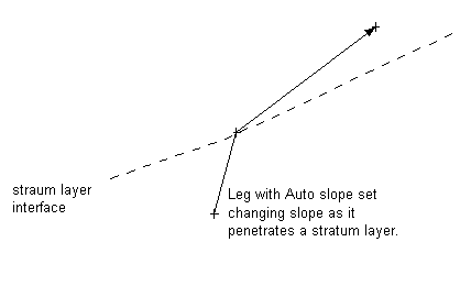
Slope: + is directed upwards – downwards. Slope can also be set to Auto indicating the slope will be determined by the ground type assign to the template station. Slopes below topo (cut slopes) are determined from the ground type(s) associated with the stratum layer(s). Slopes above topo are determined by the assigned fill type. The assigned fill type can be set in the Fill Material Assignments dialog. The default fill material is stratum layer 1 ground type.
NOTE: When the slope is set to Auto the template leg may “bend” or change slope as it penetrates a surface. See figure below.
Slope and Length properties can be assigned to Template Component Parameters. This allows them to be easily changed by non technical users./td>
|
|
2. Occurrence
|
Several flags control the creation of a leg. These flags form the leg and test the start point or end point to determine if it above or below the fragment target surface (topography).
Occurrence Flags
Exclude if starts above,
Exclude if starts below.
Exclude if ends above.
Exclude if ends below.
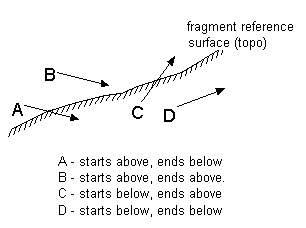
The following figure illustrates the 4 possible situations which can occur.
Figure: Possible leg positions with respect to the target surface
In the figure above leg A would not be created if either Exclude if starts above or Exclude if ends below flags were set.
Allow Singular Start Point
If this flag is set, a single point will be created, in the situation where the start point if it is valid (doesn't conflict with LEG_START_ABOVE_TARGET or LEG_START_BELOW_TARGET). The Leg point code will be assigned to the single point.
Exclude Zero Length
If this flag is set, legs with 0 length (single point or start point equals end point) will be skipped.
|
|
3. Closing/ Termination
|
Two flags control how a leg closes or terminates at the reference surface (topo).
Close to Target Surface Flag
If this flag is set the leg will be extended until it intersects the target surface. The sign of the leg slope may change to ensure the leg reaches the surface (the magnitude will remain unchanged). Not when this flag is set the Length property is ignored.
Stop at Target Surface Flag
IIf this flag is set the leg will stop when is crosses the target surface (either from above or below). Note: If this flag is set and a leg starts at the target surface it will not be created.
Allow Start at Target Surface Flag
This flag only applies if Close to Target Surface or Stop at Target Surface is set. It allows a leg to start when it begins exactly on the target surface.
|
|
4. Super-Elevation and Curve widening>
|
It is possible to add apply the current super-elevation and curve widening to individual legs.
Apply Super Elevation Flag
If this flag is set the prevailing super-elevation rate (system variable _SUPER) will b added to the slope of the leg. If the slope of the leg is 0, the resulting slope will set super.
Apply Curve Widening Flag
If this flag is set the prevailing curve widening (system variable _WIDENING) will be added to the length of the leg.
|
|
5. Sequencing and Control
|
Several flags are available to control the processing of subsequent legs and fragments.
Skip to Next Fragment if excluded
If this flag is set and the leg length is 0 or the leg is excluded because of Occurrence conditions (see above) processing will advance to the next fragment skipping all the remaining legs in the current fragment.
Skip to Next Component if excluded
If this flag is set and the leg length is 0 or the leg is excluded because of Occurrence conditions (see above) processing will advance to the next component skipping all the remaining legs in the current fragment and all remaining fragments in the current component.
|
|
6. Surface Matching
|
It is possible to control the geometry of a leg using a target surface using the following flags.
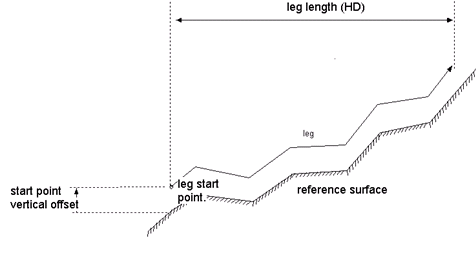
Follow target surface
If the Follow target surface flag is set the leg will match the shape of the surface from its start point for its assigned length. If the start point is on the surface the leg will be coincident with the surface. If the start point is offset from the surface the leg will follow the surface at a vertical offset.
Figure: Leg with Follow Surface property set
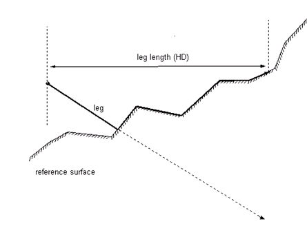
Keep above (below) target surface
If this flag is set the leg will stay above (below) the target surface.
Figure: Leg with Stay Above Surface property set
|
|
6. Adjustment (Stretching)
|
Adjust if parent surface has multiple ties
Fragment adjustment or stretching is done by setting 2 tie points (start point and end point). Each leg which has Adjust if parent surface has multiple ties set will be adjusted. Legs without this flag set will remain fixed.
If horizontal or vertical stretching is done, each adjusted leg will have its slope preserved and its length altered.
|
|
7. Fit Surface Above
|
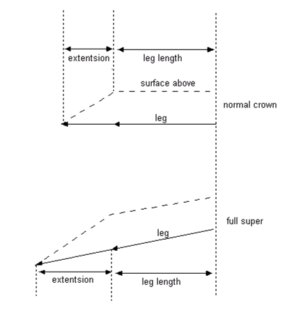
Extend to fit surfaces above
This specialized flag is used when the width of a leg depends on the widths and slopes of surfaces above it. The length of the leg is extended to account for super-elevation, and the slope of the surface(s) above. For example a leg representing the sub-grade needs to be widened to match a sub-base layer above.
Figure: Extend to Fit Surface Above property
|
|
8. Misc.
|
Apply Culvert Ditch Depth or Width Override
If this flag is set, the leg has the culvert depth (width) override added to it if it is “near” (within tolerance) of a culvert. See Culvert Editor documentation for more information.
Don't include in surface or volumes.
If this flag is set, the leg is not included in the surface (fragment surface) or volumes.
Hide
If this flag is set, the leg is hidden (has not displayed).
Probe - Retain Current Position
After each leg has been processed the current position is moved to the end of the most recent leg. This flag can be used to retain the current position.
|