Point Types
The designed road alignment is made up of a series of intersection points (IPs) connected by straight line segments (tangents). Often a curve is used as a transition between tangents. The alignment is often called the Location-Line or L-Line. Intersection points (IPs) are created using the mouse or keyboard in the Plan or Profile windows (see Interactive Operations).
In addition to intersection points (Vertical and Horizontal), Reporting points may be added anywhere along the road alignment. Reporting points cause a cross section to be calculated and are thus very useful for viewing the design at arbitrary stations. Reporting points will also improve the accuracy of the earthwork calculations, due to the increased number of cross sections. Reporting points will not change the geometry of the alignment. Reporting points can be created automatically or manually.
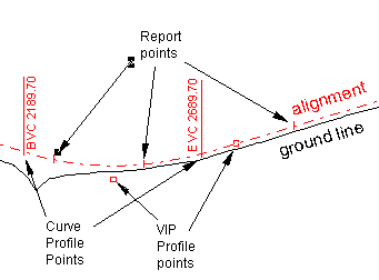
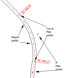
Figure 1. Point types as seen in a Profile and a Plan window
Profile Points
Vertical intersection points (VIP)
These points define the vertical alignment and are usually entered in the Profile window. These points cannot be modified in the Plan window.
Begin Curve, End Curve (BVC, EVC)
If a vertical curve is applied, the begin curve (BVC) and end curve (EVC) points lie on the alignment and each defines a calculated cross section; these points are often called Profile or L-Line points although they are not Intersection Points. The intersection point is no longer on the alignment and no longer defines a cross section.
Plan Points
Horizontal intersection points (IP)
These points define the horizontal alignment and are usually entered in the Plan window. These points cannot be modified in the Profile window.
Begin Curve, End Curve (BC, EC)
If a horizontal curve is applied, the begin curve (BC) and end curve (EC) points lie on the alignment and each defines a calculated cross section; these points are often called Plan or L-Line points although they are not Intersection Points. The intersection point is no longer on the alignment and no longer defines a cross section.
Reporting Points
Reporting points may be inserted manually in either the Plan or Profile windows; they are also generated automatically. These points do not change the geometry of the road, they do however cause cross sections to be calculated between L-line points.
Standard editable REPORT point
This was the only type of reporting point until RoadEng version 5.
These points can be created, edited and removed with the mouse when in Add/Edit Report Point mode (right click in Plan or Profile windows to change modes). They can also be created with the View | Jump to station (Ctrl-J) function.
The Auto-Generate dialog box will also create this type of reporting point; however, it has become less useful since the P-Line Survey and Auto Interval report points were added (below).
The Delete Range dialog is a good way to delete several Standard Editable REPORT points at once.
P-Line Survey points
The P-Line traverse is optional for many RoadEng products; if it doesn't exist these report point types will not exist either.
These points are optionally created on the alignment near the P-Line survey turning points (at the intersection of the P-Line perpendicular bisector with the L-Line). In a P-Line only design, the ground cross section information is recorded at these points, so it is recommended that Line Survey points always be set to Automatic in the Report Point Properties dialog box .
Auto interval points
Auto interval points 2
These points are created at equal intervals along the alignment; the interval is set in the Report Point Properties dialog box . These points are valuable for ensuring that enough cross sections are calculated between IPs to give reasonable volumes and graphics displays.
Sometimes a second interval is useful for reporting purposes in the Data window; for example you may want to calculate cross sections every 20m for accuracy, but you may want to report volumes at 100m intervals.
Culvert insertion points
These points are created at culvert locations and are useful for reporting and display.
Culvert ditch override points
Template assignment range points
Template override points
Site Preparation assignment range points
Fill assignment range points
Sub-Horizon assignment range points
These points are inserted where changes to the cross section are expected. In some cases a point will be inserted just before and just after an assignment point - this will calculate a cross section just before a change (at a bridge abutment for example) and then again just after the change.
Curve point, BC or EC
Begin and End Curve points have been mentioned above as being either Plan (horizontal) or Profile (vertical) curve points. They are listed in the Report Point Properties dialog box, however, so you can change their display properties.
When spiral horizontal curves are used, the BC and EC points are renamed TS (spiral to tangent) and ST (tangent to spiral) respectively - however they are still considered to be BC, EC points for reporting and display purposes.
These points are always inserted automatically.
Spiral curve transition points
When spiral horizontal curves are used two extra transition points are always created: SC (spiral to circle) and CS (circle to spiral).
Non-editable IP
In the Plan window, vertical IPs. BVC and EVC points can be displayed but are not editable. Similarly, in the Profile window, IPs. BC and EC points can be displayed but are not editable.
Optimizer/Cost Points
These points are created for improved optimization and costing (see also) .