Horizontal Curves Panel - Advanced Mode
The Horizontal Curves Panel allows dynamic modification of the currently selected Horizontal IP or curve (visible in the Plan Window). It is activated by clicking the  button on the Standard toolbar. See also Horizontal Curves.
To switch to Simple Mode:
Simple Mode does not includes spiral curves, some super-elevation control and design speed.
Title bar
At the top of this window is a description line showing the curve number and stationing of the currently selected curve or IP if applicable.
Curve Parameters
Note: curve parameter controls are disabled until a Circle or Spiral radio button is selected (see below).
Design Speed (km/hr or mph)
The curve specific design speed.
This value can be used to calculate a minimum Radius if Use Minimum Radius is checked (see below).
Radius (R)
Allows you to change the radius of the curve. The Curve and Tangent Parameters update instantly. If the maximum radius is exceeded, the apply button will be disabled and a warning will be reported next to the apply button.
This value can be used to calculate a maximum Design Speed if Use Minimum Radius is checked (see below).
Use Minimum Radius
When checked, you are calculating the smallest possible curve (Radius is Auto) or largest possible speed (Design Speed is Auto).
The equation used for these calculations balances radial accelerations:
(e/100 + f)g = V2/R
where:
e = super-elevation %
f = side friction factor
g = acceleration of gravity (9.81m/s2 or 32.2ft/s2)
V = speed (m/s or ft/s)
R = radius (m or ft)
Max Super-Elevation (%)
The maximum allowed super-elevation.
This field is set automatically and disabled if the super-elevation is extracted from a table (see below).
Actual Super-Elevation (%)
Super-elevation specific to this curve. You may type a value here or have the Super-elevation set automatically in the ways described below:
If the Use Minimum Radius item is checked (see above) then the super-elevation is set to the maximum allowed value (above) and can't be edited.
If the associated Auto control is checked (and Use Minimum Radius is clear) then super-elevation is calculated automatically and the edit box is disabled. The  button pops up the Auto Super-elevation Options dialog box, allowing you to define how the super-elevation is calculated.
Max Side Friction (f)
Note: this item will not be visible unless required to calculate super-elevation.
The maximum allowed side friction factor is used to calculate super-elevation if the super-elevation Auto item is checked and the calculation method is Use side friction factor (see Auto Super-elevation Options dialog box). In all other cases this field is removed from view.
This value is extracted from a table if Auto is checked (AASHTO 2001 exhibit 3-14). The associated button pops up the Auto Maximum Side Friction Factor Options dialog box, allowing you to define the table.
Actual Side Friction (f)
The Side Friction factor is the coefficient of tire friction required to to prevent a vehicle from slipping off the road, calculated from the rest of the curve parameters; alternately, it is the sideways acceleration felt by the driver (as a fraction of the acceleration of gravity, the "g-force"). The smaller the better.
The Actual Side Friction is the tire friction factor required . It is calculated using the same equation shown above in the Use Minimum Radius section.
Transition Length (BC / EC)
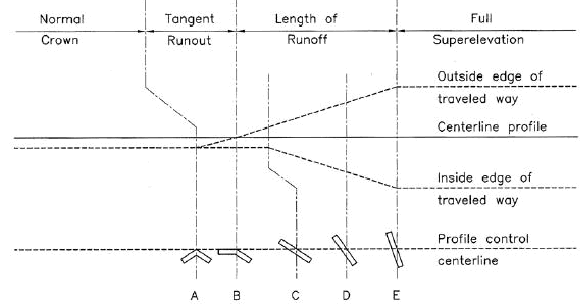
The Transition Length is both the super-elevation runoff length and the curve widening transition length. If you are not using Super-Elevation or Curve Widening, the Transition Length has no effect.
Super-elevation runoff is defined as the distance from zero cross-fall (flat) to full super-elevation to on the outside lane. If the normal cross section has a crown, then an additional transition is required from crown to zero cross-fall (the start of Super-elevation runoff ); this transition is called the Tangent Runout and it occurs outside of the transition length (see below Tangent Runout section below).
Automatic transition length
If the Auto box is checked, the Transition Length fields are disabled and the values are extracted from a table. The begin and end curve (BC and EC) transition lengths must be the same if automatic transition length is used. The button pops up the Lookup Table dialog box allowing you to view or select a table. If no table is defined the Lookup Table dialog pops up automatically when you check the Auto button.
Overlapping curves
The software will not allow you to design adjacent curves that have curved segments overlapping. However, it is reasonable to design curves with overlapping transition zones.
Note: If the transition zone of a curve overlaps that of an adjacent curve, then the super-elevation and curve widening will be calculated from a linear combination of the two curves. If you design an "S" curve (a short tangent between a Left and a Right hand curve) then the super-elevation transition will not include a crown section - the cross-fall will rotate continuously from one side to the other.
Transition Fraction
Allows you to change where the transition starts.
For a circular curve, the Super Elevation Runoff may start before the curve BC (begin curve) and end after; similarly, at the end of the curve, the transition starts before the EC (end curve) and ends after. The Transition Fraction is the amount of transition that happens outside the curve (before BC and after EC). For example, if Transition Length is 90 feet:
-
If Transition Fraction is 1.0, the Super Elevation Runoff starts 90 feet before the BC point and full super-elevation is reached at BC
-
If Transition Fraction is 0.667, a common standard, the Super Elevation Runoff starts 60 feet before BC and full super-elevation is reached 30 feet beyond BC.
Tangent Runout
Length from normal crown to the start of Super-elevation Runoff (where outside lane has zero cross fall). See diagram and description in the Transition Length section above.
If the Auto box is checked, then the Tangent Runout length is calculated so that the rate of change of cross-fall is the same as in the Super-elevation Runoff. For example if the full super-elevation is 6% and the Transition Length (= Super-elevation Runoff) is 60m, then the rate of change of cross-fall is 10m/%. If the crown slope is 2%, then the Tangent Runout will be 20m. In this case, the total transition length is 80m, 20m more than the value specified in the Transition Length field.
Widening, Inside/Outside
Small radius curves require lane widening to accommodate large vehicle off tracking. The curve widening values are added to the normal lane widths in the curve region. Inside and outside depend on the direction of the curve. For a right hand curve the inside is on the right hand side of center line while the outside is on the left. For a left hand curve, inside is left and outside is right.
Automatic Widening
If an Auto box is checked, the associated Widening field is disabled and the value is extracted from a table. The button pops up the Automatic Curve Widening Options dialog box, allowing you to read in a new Curve Widening Table and/or change the way the table is interpreted.
No Curve / Circle / Spiral radio buttons
These radio buttons define whether a curve exists.
Select Circle or Spiral to define a curve and to enable the other curve parameter controls (above).
Select No Curve to remove a curve and to disable the controls.
Apply
Saves changes to the above values, and updates alignment and all windows to show the result.
If the Apply button is not available, it means one of two things:
1 The curve has not been changed from the one already applied.
2 The curve can't be applied to the current alignment. In this event the reason will be reported left of the Apply button; for example "Curve does not fit tangents".
Toolbar
 Previous Curve, Next Curve
 Moves the current selection to the previous or next IP or curve along the horizontal alignment. Any changes made to the current curve or IP are lost unless you have Applied them.
Note that when a curve is selected, the Current Point displayed in the other windows is the EC (End Curve) point.
 Road Class Parameters
 Set/Get Default Curve
The first button saves the parameters for the current curve as the new Default Curve.
The second button retrieves the Default Curve parameters. Once your Default Curve is defined, creating a new curve requires two button clicks: Get Default Curve and Apply.
Default Curves (Vertical and Horizontal) are saved with your template table; they are saved with your document and can also be saved externally in a TPL file. Open and update your standard template table files (Normal.tpl and possibly others) to make default curves available in new projects.
 Auto-generate Curves
 Help
HelpOpens the help browser with this page displayed.
IP and Tangent Parameters
Arc Length
Shows the arc length of the current curve (0.0 if No Curve).
Delta
Shows the delta angle (change in azimuth) of the current IP/curve.
BC / EC / IP or IP- / IP / IP+
If a curve is defined, these fields display the BC (Begin Curve), EC (End Curve) and IP (Intersection Point) coordinates of the currently selected curve.
If a curve is not defined, they show the coordinates of the previous, current and next IPs.
The incoming and outgoing azimuths are also displayed.
Note that you can use the X and Y fields to change the position of the current IP. You must Apply your changes before they take effect.
 Add IP
Allows you to Add a Horizontal IP. This button is disabled if you haven't Applied changes made to the current curve/IP.
 Edit IP
Allows you to Modify a Horizontal IP. After you exit the Modify Horizontal IP dialog box, you must Apply your changes before they take effect.
 Delete IP
Deletes the current IP (and curve if defined).