Vertical Curves Panel - Advanced Mode
The Vertical Curves Panel allows dynamic modification of the currently selected Vertical IP or curve (visible in the Profile Window). It is activated by clicking the  button on the Standard toolbar. See also Vertical Curves.
Simple mode does not include sight distance and design speed.
Title bar
At the top of this window is a description line showing the curve number and stationing of the currently selected curve or vertical IP if applicable.
Curve Parameters
Note: curve parameter controls are disabled until the Parabola radio button is selected (see below).
Design Speed (km/hr or mph )
The curve specific design speed. This value is used to calculate automatic Sight Distance (see below).
Auto Checkbox
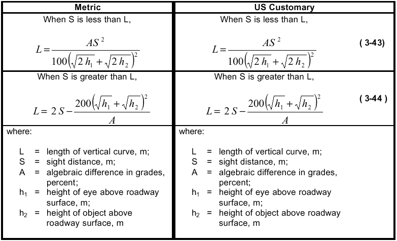
If checked, the Length and K factor are automatically calculated to provide the Sight Distance specified (see below). AASHTO 2001 exhibit 3-74, S<L equation:
Note that these equations can be derived from first principals and are therefore not specific to US standards such as AASHTO. Use the Road Class Specifications dialog to define eye and object height. Sag and crest are treated the same.
Parabolic Rate (K)
You must clear the Auto check box (above) and select the Lock K radio button to use this control.
Defines curvature in project units per %. For example, if K=10.0, then every 10m (or ft.) the grade will change by 1.0%. When you change K, the Length and IP and Tangent Parameters update instantly. If the curve does not fit the available tangents, the Apply button will be disabled and a warning will be reported.
Length
You must select the Lock L radio button to use this control.
Allows you to change the length of the curve. When you change Length, the K and Tangent Parameters update instantly. If the curve does not fit the available tangents, the apply button will be disabled and a warning will be reported.
Sight Distance
If Auto is checked, the Sight Distance is set to the stopping distance, calculated from speed, driver response time, worst case grade and deceleration.
d = Vt + V2/2(a - gG/100)
where:
d = sight stopping distance
V = speed (m/s or ft/s)
t = driver response time
a = deceleration (m/s2 or ft/s2)
g = acceleration of gravity (9.81m/s2 or 32.2ft/s2)
G = worst case grade (%)
Note that if the grade is too large or if the deceleration is too small, the vehicle won't stop - it just slides down the hill.
No Curve / Parabola
These radio buttons define whether a curve exists.
Select Parabola (the only type of curve supported) to define a curve and to enable the other curve parameter controls.
Select No Curve to remove a curve and to disable the other curve parameter controls.
Apply
Saves changes to the above values, and updates alignment and all windows to show the result.
If the Apply button is not available, it means one of two things:
1 The curve has not been changed from the one already applied.
2 The curve can't be applied to the current alignment. In this event the reason will be reported left of the Apply button; for example "Curve does not fit tangents".
Toolbar
 Previous Curve, Next Curve
 Moves the current selection to the previous or next IP or curve along the vertical alignment. Any changes made to the current curve or IP are lost unless you have Applied them.
Note that when a curve is selected, the Current Point displayed in the other windows is the EC (End Curve) point.
 Road Class Parameters
 Set/Get Default Curve
The first button saves the parameters for the current curve as the new Default Curve.
The second button retrieves the Default Curve parameters. Once your Default Curve is defined, creating a new curve requires two button clicks: Get Default Curve and Apply.
Default Curves (Vertical and Horizontal) are saved with your template table; they are saved with your document and can also be saved externally in a TPL file. Open and update your standard template table files (Normal.tpl and possibly others) to make default curves available in new projects.
 Help
HelpOpens the help browser with this page displayed.
IP and Tangent Parameters
Change in Grade
Displays the change in grade at the currently selected IP or curve (negative is a crest curve).
BC / EC / IP or IP- / IP / IP+
If a curve is defined, these fields display the BC, EC and IP coordinates of the currently selected curve.
If a curve is not defined, they show the coordinates of the previous, current and next IPs.
They also show the incoming and outgoing grades.
Note that you can use the Station and Elevation fields to change the position of the current IP. You must Apply your changes before they take effect.
 Add IP
Allows you to Add a Vertical IP. This button is disabled if you haven't Applied changes made to the current curve/IP.
 Edit IP
Allows you to Modify a Vertical IP. After you exit the Modify Vertical IP dialog box, you must Apply your changes before they take effect.
 Delete IP
Deletes the current IP (and curve if defined).