Culvert Editor Panel
The Culvert Editor Panel allows dynamic modification of the currently selected culvert. See also Culverts.
L-Line Station List
Culverts are referenced by L-Line station. Click with the mouse on the culvert you wish to modify.
Note that the L-Line station of a culvert will change when horizontal alignment is modified; the physical location of the culvert will not change unless the alignment is modified near the culvert. If the horizontal alignment is changed near the culvert, the physical location must change and (if a P-Line is defined) the P-Line station of the culvert will also change by a small amount.
Add
Properties
This button pops up the Culvert Properties dialog which allows you to change the size of the culvert and some other settings. Click the Apply button after making any changes to update all windows.
Delete
Deletes the selected culvert.
Import (Not visible if no P-Line defined)
Apply
This button will update the display of all windows with any changes you've made in the Culvert Editor Panel.
Get / Save Defaults
This pair of buttons allows you to set up the culvert parameters at one culvert, put those parameters in memory by pressing Save, then select another culvert or range of culverts and apply the parameters by pressing Get.
Description
Enter a description of the culvert. The description will appear in the Data Window report of as a plan or profile label. If you wish to enter more than 1 line press <Enter> at the end of each line.
Length
Auto (Length)
If the Auto checkbox is selected, the Location module attempts to determine length of the culvert. NOTE: It is often necessary to override this calculation. If Auto is disabled you can enter the length of culvert left and right. Selecting the "+" button pops up the Culvert Auto Length Calculation dialog that allows you to add additional length to the automatically computed length.
Left (Length)
If Auto is disabled, you can enter the length of the culvert left of the L-line. This length is the true length of the culvert not the projected length shown on the cross section (see Culverts for more information).
Right (Length)
If Auto is disabled, you can enter the length of the culvert right of the centerline. This length is the true length of the culvert not the projected length shown on the cross section (see Culverts for more information).
Vertical Position
Depth
Enter the depth in project units. The interpretation of this field depends on the currently selected Vertical Position radio buttons as described below.
Cut Depth at C/L to Structure Bottom
This option determines how the depth is used to vertically position the bottom of the culvert relative to original topography. E.g. a depth of 0.0 would position a pipe culvert on the ground, and a depth of 0.5 would position the culvert 0.5 meters (or feet) below ground.
Fill Depth at C/L
This option determines how the depth is used to vertically position the top of the culvert relative to the finished road grade (subgrade plus surfacing). E.g. a depth of 0.5 would position the top of a pipe 0.5 meters (feet) below the finished road surface.
Minimum Fill Depth
This option determines how the depth is used to vertically position the top of the culvert relative to the lowest point of the finished road grade on the section. E.g. a depth of 0.5 would position the top of a pipe 0.5 meters (feet) below the shoulder point on the finished road surface.
Attach to Upper Ditch / Catch Point
This option disables the depth measure and positions the culvert at the ditch point or at the slope stake point.
Orientation
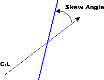
Skew Degrees
The skew angle of the culvert can be set if Auto is not selected. The skew angle is measured in degrees from the L-line counterclockwise 0-180.
If Auto is selected, the Skew angle is determined differently depending on the type of culvert (creek crossing or cross drain). For creek crossings the skew angle is determined from the azimuth of the creek as entered in the traverse document (see Online help for Survey/Map for more information). For cross drains the angle is set based on the following formula:
Skew = 90 - (CLGrade - 3) * 3
Where CLGrade = grade of the road.
Figure 1. Skew Angle
%Gradient
The gradient of the culvert can be set if Auto is not selected. The gradient % is measured from horizontal. The gradient is measured in the plane of the skewed culvert not the projected cross section.
If Auto is selected, the gradient % is determined differently depending on the type of culvert (creek crossing or cross drain). For creek crossings the gradient % is determined from the gradient of the creek as entered in the traverse document (see Online help for Survey/Map for more information). For cross drains the gradient depends on the Vertical Position options above.
If SemiAuto is selected the gradient can be entered manually. Sign (either negative or positive) does not matter because the culvert will always face in the down-slope direction.
If SemiAuto is unselected direction and gradient can be changed