Grading dialog
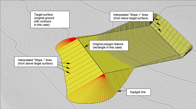
Slopes lines are projected at user specified angles from the selected feature to the 'Target Surface'. A daylight line is drawn where the slope lines intersect the target surface. Slope lines are created at each feature point and additional interpolated points.
Orientation
Left/Right/Both - side(s) of the feature from which to perform the grading.
Target Surface
Target surface definition. This is the surface to which the feature is projected.
File requires a Terrain file containing a TIN surface. Choose a background file from the drop list or Browse for another Terrain File.
Elevation allows you to grade to specific Elevation.
Current uses the TIN surface in the current terrain as the target surface.
Softree recommends against the Current option; it is better to have the target surface in an external file so that you can create a graded surface without incorporating the target surface points.
Left (or Right) Slopes / Cross Section
Slope + defines the slope for projections that start below the target surface. If your target surface is the original ground, then this will be a cut slope.
Slope - defines the slope for projections that start above the target surface. If your target surface is the original ground, then this will be a fill slope.
Use Template (Check box and "+" button)
Set this check box to use template components to define the shape of the projected slope lines.
Slope Lines
Interpolate - If checked, extra slope lines are created between graded feature points at the Spacing provided (see image above).
TIN / Volumes
Set Daylight to TIN boundary - The Daylight feature(s) is(are) formed by joining the points where the projected slope lines intersect the target (see image above). If this control is checked, this feature will have the TIN boundary property set. This will prevent TIN surface triangles from being formed outside the Daylight line
Calculate TIN - If checked, the TIN surface is calculated after the projection. Clicking on the plus sign allows you to set the TIN modelling parameters through the Terrain Calculation dialog .
Calculate Volumes - If checked, the volumes are calculated after the projection. The volume between the current Terrain and the Target surface is calculated. This option is only available when the target surface is a file.
Auto Balance
This option automatically adjusts the elevation of the graded feature, to match the specified Surplus Volume.
Surplus volume - this target excess volume desired = (Cut - Fill). A value of 0 corresponds to balanced cut and fill volumes. A positive value indicates more cut than fill. A negative value indicates more fill than cut.
Cut/Fill Expansion Factors - these factors (multipliers) are applied to the cut and fill volumes.
Note: - If more than one feature is selected, the current feature will be the graded feature and all selected features will be vertically shifted to achieve the required volume