Traverse Coordinate Adjustments
The spatial location of a traverse is based on 3D coordinate Northing, Easting and Elevation (x,y,z) stored with each station.
Setting Up the Coordinate System
When you first create a traverse, the starting station coordinate is initially set to (0,0,100).
It may be necessary to "tie" the traverse to a map coordinate system such as UTM. In this case you can change the default (0,0,100) coordinate to the known UTM coordinate.
Absolute Coordinates
When survey notes are entered the x,y,z location of each station is automatically calculated. You can override these calculated coordinates by setting them explicitly using the menu Traverse | Get/Set XYZ Coordinates. When the coordinate of a station is explicitly set this way it is called an Absolute Coordinate. Absolute Coordinates are points which have been spatially fixed in x and y only, in elevation only, or in x, y and elevation.
The first station in a traverse is always absolute. The coordinates between absolute stations are automatically adjusted to minimize the deviation from the raw survey data using the Compass Rule. This adjustment is 3 dimensional and accounts for deviations in elevation.
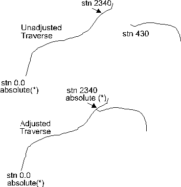
Figure 1. Traverse before and after adjustment
In the figure above the traverse is adjusted at station 2340 to join a tie line. This procedure can be done in the Survey Window as follows.
1. Determine the tie line coordinates at station 430 using Traverse | Get/Set XYZ Coordinates function.
2. Set station coordinates on the traverse at station 2340 to match the coordinates determined in 1. Use Traverse | Get/Set XYZ Coordinates.
3. Coordinates on the traverse in between station 0 and 2340 will be adjusted based on the Compass Rule. Station 0 and 2340 will be absolute, indicated by an '*' in the Survey Window.
NOTE: Absolute stations appear in the Survey Window with a '*' beside them. The 1st station in a traverse is always an absolute coordinate.
It is possible to adjust the underlying x,y,z coordinates of a traverse in the map window. This is useful for such things as closing a boundary traverse or joining a spur road to a main road. These adjustments are done by using the Map | Adjustment menu function.
NOTE: Coordinate adjustments never alter the field notes only the underlying coordinates. Two types of adjustment operations are allowed: Closing and Shifting.
Closing Operation in Map Window
A closing operation is commonly used to join a traverse head to tail forming a closed polygon.
Boundary Closing
The first station in a traverse is always absolute and will remain fixed during a closing operation. The coordinate of the last station is changed to be coincident with the first station. Intermediate station coordinates are then adjusted using the Compass Rule.
Closing operations can also be used to join or 'tie' features together. Consider a block boundary which begins at station 300 on a road traverse and ends at station 1260.
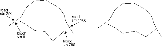
Figure 2. Road and Block Closing
In the road and block closing in the figure above, station 0.0 on the block was already joined at station 300. The end of the traverse was set (using Map | Adjustment) to the (x,y,z) coordinate of station 1260. The coordinates for the intermediate stations on the block boundary were adjusted automatically using the Compass Rule.
It is possible to use the closing operation to make more complicated multiple adjustments (tie lines, photo ties etc.). When using the closing operation it is important to remember the following rules.
·The first station in a traverse is always absolute, however its coordinates may be user defined.
·Whenever a coordinate on a traverse is changed using the closing operation, it becomes an absolute point.
·Points in between absolute points are derived using the Compass Rule.
Shifting Operation in Map Window
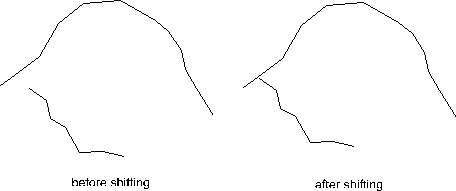
The shifting operation moves every point on a traverse the same distance in the same direction. It is useful for connecting traverses together.
Figure 3. Shifting Operation
The coordinates of the traverse can be explicitly changed at any time using the Traverse | Get/Set XYZ Coordinates menu or indirectly using the Traverse | Join to Existing Traverse menu.
Error Calculations
The % error is calculated when a traverse is closed. This error is the deviation length between absolute stations divided by the total distance between the absolute stations. For a closed polygon this error is usually the length deviation between head and tail, divided by the total length of the traverse (provided the traverse has no other absolute coordinates). The 2 dimensional and 3 dimensional (includes elevation) errors are reported. If a large difference exists in 3D error but only a small difference in 2D error then it is most probable that a slope % has been entered incorrectly or with the wrong sign.