Export to Terrain dialog
This dialog allows you to export a Location file to the Terrain module. You can access this function from the from File | Save As item by choosing Terrain File (*.ter) from the Save File as Type list. .
This dialog also allows you to control the way the designed alignment is exported to 3D window in the Location module. To access the dialog in 3D options click the "+" button next to Display in TIN Model section.
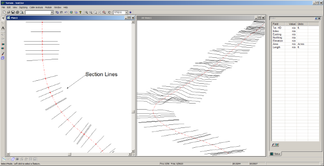
Figure: Terrain Created from Location
Horizontal Alignment(s)
Provides for selection of one or more alignments. The "+" button allows for selection of individual alignments.
Station Range
Allows you to specify a range of stations to export. Select All for the entire design.
Point Types
Allows you to specify which cross sections will be exported. This applies to Section points (if enabled) and Linear Features from Template codes . Press the "+" button to add and remove cross section types.
Sections / Surfaces
Include Sections
If selected, cross section points corresponding to the selected surface are exported. If Final Surface is selected, all cross section points will be exported.
Surface (combo box)
Allows you to choose which surface you which to export. Select one of the template surfaces or Final (Merged) Surface to export the completed road cross section.
The following options apply only if if Final Surface or Stripped Surface is selected for export.
Section Offset
Allows you to a offset from either CL or the slope stake to extend the cross section. This option is only available if Final Surface is selected for export.
From CL
If selected, the section Offset will be measured from road centerline.
From SS
If selected, the section Offset will be measured from the slope stake position.
Connected
If selected, the section lines will be connected, otherwise they will be isolated points.
Surface Limits
If selected, a linear feature is saved along the edge of the surface. This feature is useful for limiting the extent of a TIN model. NOTE: This option is only available if All point types are selected.
3D
The feature will be saved with the "Elevations" property set (see Terrain module documentation for more information).
Modeled
The feature will be saved with be the "Modeled" property set (see Terrain module documentation for more information).
Breakline
The feature will be saved with the "Breakline" property set (see Terrain module documentation for more information).
Boundary
The feature will be saved with be "TIN boundary" property set. It is particularly important to select Boundary if you wish to Create a TIN Model (see Terrain module documentation for more information).
Linear features
Centerline
If selected, the road centerline will be exported as a linear feature. This feature will have properties 3D, Modeled, Breakline as indicated (see description above).
Linear features from Template Codes
This option allows you to export any any point code defined on the template as linear features. For instance choosing REL and RER would export the road edges. The spacing of the points depends on the items selected in Point Types above.
Add
Use this option to add point codes.
Remove
Use this options to remove point codes.
3D, Modeled, and Breakline properties can be set separately for each point code feature.
Create TIN model
Set this check box to create a surface model before export. This is not available if you are exporting to the clipboard.