Corridor Surfaces
Overview
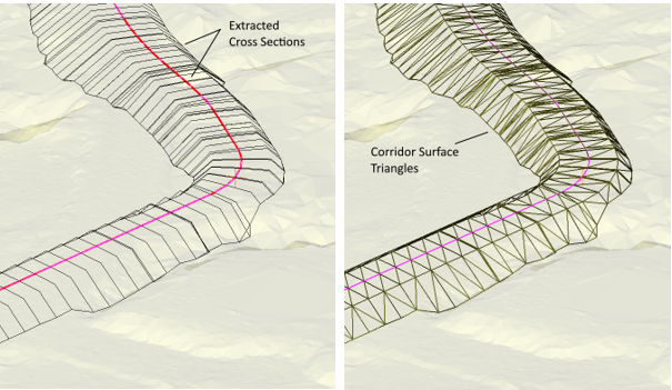
Corridor surfaces are TIN surfaces created automatically during the processing of a horizontal alignment.
The process for creating a Corridor Surface is as follows:
1) Cross sections are calculated.
2) Each cross section surface is extracted and set to be a breakline.
3) The limits of each cross section are used to form a TIN boundary.
4) The Corridor TIN surface is calculated.
Figure: Corridor Surface TIN model created from Cross Sections
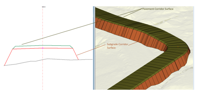
Each Corridor surface corresponds to a horizontal alignment and a template layer. It is possible to create multiple Corridor surfaces for a single horizontal alignment.
Figure: Multiple Corridor Surfaces from A Single Horizontal Alignment
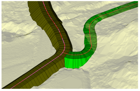
It is also possible to create corridor surfaces from different horizontal alignments.
Figure: Multiple Corridor Surfaces from Different Horizontal Alignments
Corridor Calculations and Construction Sequence
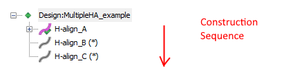
Once a corridor surface has been created it can be used referred to in further corridor calculations. For example, suppose we have 3 horizontal alignments (H-Align_A, H-Align_B and H-Align_C).
Figure: Construction Sequence
In the example above:
- Corridor surfaces created in H-align_A can be used in H-align_B and H-align_C.
- Corridor surfaces created in H-align_B can be used only in H-align_C.
- Corridor Surfaces created in H-align_C can not be used in other corridor calculations.
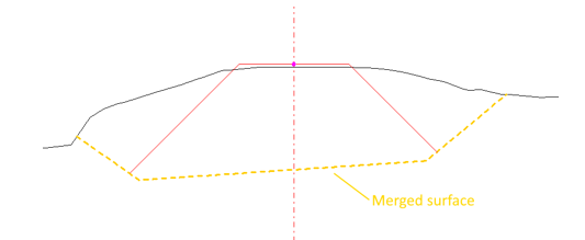
Merged Surfaces
It is possible to incorporate a Corridor Surface into the merged surface. In this case, after the surface is calculated it will be included in the OG (merged) surface for future alignment calculations.
In the example below the merged surface trench (yellow) has been created by another corridor operation.
Figure: Merged Surface created from another corridor